11 Mar 2026
Watching a class of undergrad CS students work on a midterm exam for a C programming course was a good motivator to start putting together this list of “Essential CS Lore”. I believe that any CS student or practitioner (or adjacent), as well as anyone interested in the discipline should have detailed knowledge of all of these!
Movies/TV
- Mr Robot (2015) – Widely considered the most technically accurate portrayal of hacking on television. Shows real tools, realistic attack vectors, and plausible social engineering. Explores hacker culture, cybersecurity ethics, and corporate power.
- The Matrix (1999) – Introduced the mainstream world to philosophical questions about simulation, reality, and AI. “Red pill / blue pill” became a cultural meme far beyond CS.
- Sneakers (1992) – A cult classic about penetration testing before the term existed. Explores cryptography, surveillance, and social engineering.
- Wargames (1983) – One of the first films about computer hacking and network access. Helped inspire real-world interest in cybersecurity. Famous line: “The only winning move is not to play.”
- Tron (1982) – The first major film to visualize programs as characters and computers as worlds. Hugely influential on how people imagine “inside the machine.”
- 2001 A Space Odyssey (1968) – Introduced HAL 9000, one of the most iconic fictional AIs. Explores AI reliability, autonomy, and failure.
Books
- Daemon by Daniel Suarez (2006) (and its successor: Freedom) – Proved that “Hard Sci-Fi” could be written with 100% real-world code and protocols. Visualized how AR and gamification could replace traditional government.
- Cryptonomicon by Neal Stephenson (1999) – Deeply influential in cryptography and hacker culture. Frequently cited in startup and security circles.
- Snow Crash by Neal Stephenson (1992) – Popularized the concept of the Metaverse. Mixes distributed systems, linguistics, and computer viruses as metaphors.
- The Cuckoo’s Egg by Clifford Stoll (1989) – A true story about tracking a hacker in the early internet. Shows early intrusion detection and network tracing.
- Neuromancer by William Gibson (1984) – Defined the cyberpunk genre. Introduced the word “cyberspace.”
- Hitchhiker’s Guide to the Galaxy by Douglas Adams (1978–1980) – First released as a radio sitcom broadcast and later adapted to books, TV shows, and even a video game. The Answer to the Ultimate Question: 42 is one of the most famous jokes in CS culture. Introduced ideas about supercomputers answering existential questions. Deeply embedded in programmer humor and references.
- Foundation by Isaac Asimov (1942–1950) – Introduces psychohistory, a fictional predictive science that resonates with modern data science and algorithmic prediction.
Online
- BOFH diaries – Satirical stories about an abusive system administrator. Reflects real frustrations of system administrators.
- The Jargon File (1975-2012) – The name says it all; a large file containign hacker slang. Stopped being actively maintained around 2012. Site is unreliable and breaks often.
- user friendly – One of the earliest long-running sysadmin/programmer comics. Captures 90s–2000s internet culture.
- xkcd – Probably the most referenced comic among programmers. Explains complex technical ideas through humor.
Honorable mention
- Dilbert by Scott Adams – Satire of corporate engineering culture. Many developers identify with the bureaucracy and absurd management.
- PhD Comics by Jorge Cham – Captures academic CS culture: grad school, advisors, publishing pressure.
- Computerphile – arguably the most universally referenced CS YouTube channel.
- The Cathedral and the Bazaar by (Eric S. Raymond) – Influential in open-source culture. Foundations for GNU Open Source Licenses.
What do you think? What’s here that should not be here, or what’s missing?
18 Jan 2026
TL;DR. Check wiring before blaming software.
After completing the build of my 8-bit computer based on Ben Eater’s
kits, I have now started work on his 65c02
project.
I ran into some issue with the Arduino
Mega,
but decided to skip that bit for now. Instead, I went on to build the entire
thing and proceeded with loading Wozmon on it directly.
To absolutely nobody’s surprise, that didn’t work. So; back to taking a more
incremental approach.
Step 1: I built the module with the 65C02, the ROM chip and the versatile
input/output adapter. Then, I customized Ben’s sample
blink.s program to make it into a nice
Cylon (or Knight
Rider’s
KITT) woosh. That worked! In case you’re
interested, that bruteforce code is below. I named the file myblink.s.
Step 2: The next step was to connect up the display module and see if
that worked with Ben’s
hello-world.s program. No
issue!
Step 3: Now on a roll, it was time to hook up the RAM and run
hello-world.s again. Bingo! That worked. Next, let’s run
hello-world-final.s.
And for sure, that did NOT work.
Step 4: Of course, rather than second-guessing my own build, as any good
software engineer, I blamed the failure to run on somebody else faulty code.
All I needed to do was write a short test program to demonstrate that I was
right. So, I decided to do just that.
Basically, I took the first four low bits of PORTA and hooked up LEDs to
them. The first two bits were toggled by writing directly to PORTA. The
second two used three subroutines to toggle the next two pins. That way, I
can see that the program is running, and since we already demonstrated that
it was fine without needing a stack, it was a good control.
Clearly, this didn’t work either. The first two LEDs toggled just fine, but the
last two didn’t. Commenting out the subroutine calls confirmed that Ben’s
program was fine after all; it really must have been my build instead of Ben’s
code. Who would have thought?
Anyway; after carefully checking all address lines (no issue), all data
lines (no issue), and the control lines, I finally identified that my
read/write pin was off-by-one on the 65C02.
Running the program again quickly demonstrated that my four LEDs now were
toggling nicely.
That meant that the all component involved were working (i.e., the 65c02,
the RAM, the ROM, the versatile I/O adapter, and the NAND gates.
And for sure, hello-world-final.s now also worked nicely.
Step 5: All that was left now was replacing the 555-based timer with the
1MHz crystal, and we’re all good.
Lesson learned: Start troubleshooting layer 1.
Next up: Serial interfacing!
myblink.s
 .org $8000

reset:
  lda #$ff
  sta $6002

  lda #$50
  sta $6000

loop:
  lda #1

ltr:
  sta $6000  ; output value
  cmp #128   ; if we are on the last bit
  beq rev    ;
  asl        ; shift left
  jmp ltr
rev:
  sta $6000
  cmp #1
  beq ltr
  lsr
  jmp rev

  .org $fffc
  .word reset
  .word $0000
ram-test.s
PORTB = $6000
PORTA = $6001
DDRB  = $6002
DDRA  = $6003

 .org $8000

reset:
  lda #%00001111        ; set least signficant bits on port A to output
  sta DDRA

loop:
  ; first try without using ram
  lda #%00000001
  sta PORTA

  lda #%00000010
  sta PORTA

  ; then try with ram
  jsr pattern1
  jsr output
  jsr pattern2
  jsr output
  jmp loop

pattern1:
  lda #%00000100
  rts

pattern2:
  lda #%00001000
  rts

output:
  sta PORTA
  rts

  .org $fffc
  .word reset
  .word $0000
06 Jan 2026
In my previous post, I announced that build of Ben Eater’s 8-bit
Computer is done. That means it is now time to put it
through its paces!
My goal is to develop a sequence of programs that will test every opcode that
is available to us in the basic instruction set.
The total instruction set includes:
-
LDI x: Load the value x directly into the A-register
-
LDA x: Load the value specified at address x into the A-Register
-
STA x: Store the value in the A-register into memory location x
-
HLT: Stops program execution
-
OUT: Prints the value in the A-register to the display
-
ADD x: Adds the value stored in memory location x to the value in the
A-Register and store the result in the A-register.
-
SUB x: Subtracts the value tored in memory location x from the value in
the A-Register and store the result in the A-register.
-
JMP x: Continue program execution at address x.
-
JZ x: Continue program execution at address x if the Zero-bit is set in the flags.
-
JC x: Continue program execution at address x if the Carry-bit is set in the flags.
Program 1
0:  LDA [14]
1:  ADD [15]
2:  OUT
3:  HLT
14: #28
15: #14
This program test: LDA, ADD, OUT, and HLT. If you enter the program and get
the value 42 printed on the display when you run it, those instructions work.
This is the program that Ben uses in his videos.
Program 2
0: LDI #1   ;   0101 0001
1: OUT      ;   1110 0001
2: ADD [15] ;   0010 1111
3: JMP 1    ;   0110 0001
15: 0000 0001
Start counting at 1 and increment the counter each time the program loops.
This program adds tests for LDI and JMP. If your program starts counting at 1, shows the
value on the display, and then continues to the next number, the instructions
work.
Program 3
0: LDI #15   ;  0101 1111
1: OUT      ;   1110 0001
2: SUB [15] ;   0011 1111
3: JZ 0     ;   1000 0000
4: JMP 1    ;   0110 0001
15: 0000 0001
Start counting at 15 and count down to 0. When the counter reaches 0, start
back at 15. After each counter update, show the result on the display.
This program adds tests for SUB and JZ. The expected behavior is that
you’ll see the counter count down from 15 to 0 (inclusive) and then restart at
Program 4
0: LDI #10  ; 0101 1010
1: STA #15  ; 0100 1111
2: LDI #5   ; 0101 0101
3: LDA #15  ; 0001 1111
4: OUT      ; 1110 1111
5: HLT      ; 1111 1111
I couldn’t really come up with a fancy one, so I kept it simple. This programs
loads the value 10 into the A-register, and the stores it at memory address 15.
It then changes the A-register to 5, followed by retrieving address 15 and
storing it into the A-register. Lastly, the program ends.
This program adds tests for STA. If the display shows the number 5, there is
a problem. If it shows the number 10, we’re all good to go.
UPDATE: I forgot to check for JC. To be continued!
03 Jan 2026
It is alive!
The 8-bit computer works! Well– in any case: some parts of it do.
The program that Ben uses in his videos works! It outputs 42 (as it should)
0:  LDA [14]
1:  ADD [15]
2:  OUT
3:  HLT
14: #28
15: #14
That means that the commands: LDA, ADD, OUT, HLT are implemented correctly!
In addition to my previous lessons-learned, here are some more insights:
-
Build using the schematics. Using the videos is fine as reference, but they
should not lead.
-
Redraw the schematics if you make changes to the circuits. For example, you
want to do this if you switch out components. I used KiCad.
-
Don’t be afraid to mark up schematics. I marked them quite a bit. Sometimes
with ‘L’ and ‘R’ to denote components (left or right), or with arrows to
denote direction of data flow. It helps understand what’s actually going on,
which is necessary to troubleshoot.
For example:
-
Pull all unused inputs high or low so that the corresponding output is high.
I used 10k resistors.
-
Pull all outputs on the microcode EEPROMs high or low. Active low control
signals get pulled high; active high control signals get pulled low. I used
10k resistors.
-
Add current-limiting resistors to all LEDs. I forgot the program counter
ones, which caused their 74LS245 to not behave nicely. This does mean that
you’ll have to move stuff around on the board; there simply isn’t enough
space to put LEDs with the current-limiting resistors to keep them where Ben
has them in his videos.
-
Don’t skip any wires ;) It took quite a bit of troubleshooting to realize
that I never connected the 74LS283s in the ALU to the A-register. Oops.
-
When you get to the stage that you have all of the boards in use, hot-glue
them to a piece of 1/8” plywood. That allows you to move your project
without worrying that things are going to shift. I made mine to be the
height of the computer, but gave myself about 10” in either side (left,
right) so I can move my pliers, multimeter, etc. with the project.
What’s next?
Write code to test all the instructions! I’ll post updates about that too.
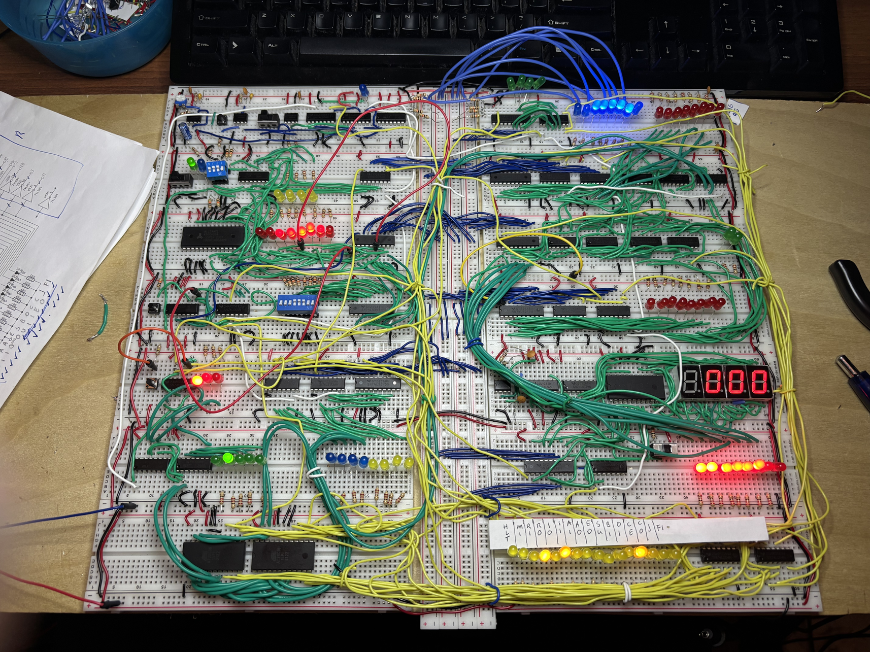
22 Dec 2025
I have decided to build Ben Eater’s 8-bit Computer
during Winter break. The initial wiring is done. Of course, that didn’t go
without issues.
-
I ran out of wire. That’s my own fault; I changed the layout of the board
and made some miscuts. I had other colored wire laying around, but that
was not single-core. You’ll see some of the green stuff in the
bottom-left (see below). Since it is not solid core, it also doesn’t hold
shape as well.
-
I fried a ton of LEDs in the process. So, despite reading Helpful Tips
and Recommendations for Ben Eater’s 8-Bit Computer
Project
and not using current-limiting resistors everywhere, I went ahead and did
that.
This also solved the problem of low voltages, causing inputs not to reach
TTL levels.
LEDs were easy to get on Amazon.
-
I must have also killed some other components along the way. I know of at
least one 74LS245 and one 74LS04. Amazon to the rescue again for a set of
various
components and for a bunch of new
inverters.
-
The DIP switches just didn’t want to stay in the board, so I ended up
having to solder some header pins to them. That fixed the issue
completely.
-
One of my memory chips was bad. Reddit to the rescue. Thanks to
The8BitEnthusiast on the r/beneater subreddit, I found an updated
schema using a newer memory chip in the r/beneater Subreddit.
Right now, I’m troubleshooting. It seems that the 47LS173 in the instruction
register is getting all the correct input voltages, but doesn’t actually
output the bus signal to the output pins.
When I remove the chip from the board and test it in isolation, it does
work, however.